
“Which is better, vacuum brazing or friction stir welding?” is the question we get asked. It is not quite the right question. In practice the choice is made for you by two things you have almost certainly already decided — the base material, and whether the plate needs internal fins. Once those are fixed, the joining method usually follows. The cases where you have a genuinely free choice are narrower than most comparisons suggest.
It is also worth noticing who writes these comparisons. FSW equipment builders publish material explaining why FSW wins. Brazing houses publish material explaining why brazing wins. We operate from a manufacturing base in China and run both processes on our own equipment, which removes one source of bias but not all of them — we would still rather sell you a plate than tell you to bolt a cover on. So the rules below are written to be checked against your own drawing rather than taken on trust, and there is a section on the case where you should not buy a welded or brazed plate at all.
The short version
- Aluminium, channels machined or skived into the base, series quantity — friction stir welding.
- Copper, or any design that needs folded-fin inserts or a multi-layer stack — vacuum brazing.
- Prototype, moderate pressure, or a plate you will want to open again — bolted cover with an elastomer seal. Revisit the joint when the design freezes, not before.
Everything below is why, and where the rules break.
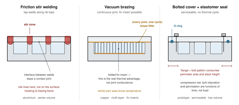
What each process actually does
Friction stir welding
A rotating tool — a broad shoulder with a shorter profiled pin below it — is plunged into the joint and traversed along it. Friction under the shoulder and shear from the pin bring the metal to a plastic, not molten, state; the pin stirs material from both sides together while the shoulder forges it closed behind the tool. No filler metal, no melting, no shielding gas, no flux.
On a cold plate the usual arrangement is a machined base carrying the flow channels, a flat cover plate laid over it, and lap welds run along the top of every channel wall, plus a weld around the perimeter. Two consequences are worth holding on to. First, the joint exists only where the tool went — everywhere else the cover is simply sitting on the base. Second, the tool needs to reach the whole weld path from one accessible face, along a straight or gently curved line, with a rigid anvil underneath. FSW also needs real axial force; a general-purpose machining centre without adequate Z-axis rigidity and force control produces inconsistent welds, which is why dedicated FSW machines exist.
One detail that surprises people the first time: a conventional fixed-pin tool leaves an exit hole where it retracts at the end of the weld. It has to go somewhere. On a well-planned plate it goes into a sacrificial tab or a region outside the sealed volume. If nobody plans for it, it ends up somewhere you did not want a hole.
Vacuum brazing
The complete assembly — base, filler metal, any fin inserts, cover — is stacked in a fixture and loaded into a vacuum furnace. The chamber pumps down, then the whole part is heated above the liquidus of the filler and below the solidus of the base metal. The filler melts and is drawn into the joint gaps by capillary action. Every joint in the assembly forms in the same cycle.
No flux is required, because there is no oxygen for a flux to deal with. For a cold plate this matters more than it sounds: flux residue trapped inside a sealed water channel is a corrosion source you cannot inspect, cannot rinse out, and will not find until the plate has been in service for a while.
The two consequences here: the entire part goes to brazing temperature, not just the joint line — and the part has to fit inside the furnace hot zone.
Why aluminium usually goes to FSW
Three reasons, in descending order of how often they decide it.
Aluminium is easy to stir. It plasticises at a temperature and forging force that ordinary hot-work tool steel survives. H13 tooling is cheap, lasts, and is re-machinable. That keeps the per-part cost of the weld low once the fixture exists.
Aluminium brazing has an uncomfortably narrow process window. Al-Si filler alloys sit around a 577 °C eutectic, and typical cold plate braze cycles run near 590–600 °C. Meanwhile the solidus of 6061 is roughly 582 °C. That is not much margin between “the filler flows” and “the part starts to melt”. 3003 (solidus around 643 °C) and 6063 (around 615 °C) leave far more room, which is why they are the more common core alloys for brazed aluminium plates. If your drawing specifies 6061 and vacuum brazing, a good shop will ask you about it. A less good shop will not.
6061-T6 does not come out of a braze cycle as T6. It comes out effectively annealed, and getting temper back means a post-braze solution treatment and age — which means a quench, which is where flatness goes. FSW has its own version of this problem: heat-affected zone softening either side of the weld line in 6xxx alloys. But that softening is local to the weld track, not global to the part, and on a cold plate the weld track is rarely the structurally critical region.
Why copper usually goes to vacuum brazing
Copper FSW works, but it is expensive. This is worth stating clearly because you will find papers and case studies showing successful copper friction stir welds — nuclear waste containment canisters and sputtering target backing plates are the classic industrial examples. The process is real. The problem is economics. Copper’s thermal conductivity carries frictional heat away from the tool faster than aluminium does, which makes it hard to hold a stable weld temperature and pushes you toward slower traverse speeds and higher heat input. And H13 tooling wears rapidly against copper; production tooling moves to tungsten-based alloys or PCBN, which is an order of magnitude more expensive and needs replacing on a schedule. Slower cycle plus costly consumable tooling is a bad combination at the quantities most cold plate programmes run.
Copper brazes forgivingly. Base copper melts at about 1083 °C. Silver-based BAg fillers run roughly in the 780–870 °C range; BCuP fillers run lower. That is a wide, comfortable margin with good wetting behaviour — the opposite of the aluminium situation described above.
Copper has less to lose. A copper cold plate is specified for conductivity, not strength, so the full anneal a braze cycle delivers usually costs nothing that matters. Two caveats, both cheap to design around and both routinely missed:
- Tapped holes and mounting bosses in fully annealed copper are weak. If the plate carries a bolted load — a cold plate almost always does — plan for threaded inserts rather than tapping soft copper directly, or move the load path into a separate bracket.
- Specify oxygen-free copper if the plate will be furnace brazed. C10100 or C10200 rather than C11000 ETP. Oxygen-bearing copper is vulnerable to hydrogen embrittlement in any furnace atmosphere containing hydrogen. In a true high vacuum the exposure is much lower, but the specification costs little and the failure mode — intergranular cracking you find after assembly — costs a lot.
Filler cost is the one real penalty. Silver-bearing filler is a material cost that scales with joint area and does not amortise over quantity the way tooling does.
Five comparisons that actually matter
The bolted-and-sealed option is included as a peer column rather than a footnote, because for a meaningful share of the drawings we are sent it is the correct answer.
| Friction stir welding | Vacuum brazing | Bolted cover + elastomer seal | |
|---|---|---|---|
| Joint strength | Solid-state bond, stir zone approaching base metal properties. Lap geometry gives up effective cross-section to hooking and cover thinning. HAZ softening in 6xxx alloys. | Filler is weaker than the base metal, so joint shear strength is a fraction of base — but the joint area is continuous and large, so total capacity is usually ample. | Bolts carry all structural load. The seal carries none. Capacity is whatever your bolt pattern says it is. |
| Leak integrity | Hermetic when parameters are right. Risk is concentrated in the lap interface, not the visible surface. | Hermetic and continuous around the full joint. Risk is voids and incomplete capillary fill. | Bounded by the elastomer: compression set, permeation, and bolt relaxation are all time-dependent. |
| Thermal path | Metallurgical bond along the weld tracks only; the unwelded portions of the cover-to-rib interface stay a contact joint. | Continuous filler layer at every interface, which is what makes internal fin inserts possible. | Cover-to-base is a dry contact interface throughout. |
| Cost structure | Fixture cost, then machine time roughly proportional to total weld path length. | Fixture cost, plus a furnace cycle that costs nearly the same whether the load is full or not, plus filler material. | Lowest tooling cost. Highest part count and assembly labour per unit. |
| Small quantity | Fixture cost dominates and is hard to hide at low volume. | Worst case: a two-piece prototype pays for a whole furnace cycle unless it can share a load. | Best. This is the honest reason most prototypes are bolted. |
The bottom row is worth more attention than it usually gets. Which of these three is cheapest changes completely with quantity — the cost shape of each construction is set out separately, along with the levers that bring a small-batch price down.
Copper adds a constraint that aluminium does not: standard ETP copper carries residual oxygen and can embrittle in a hydrogen-bearing furnace atmosphere, which is why copper grade selection for brazed assemblies belongs in the drawing rather than in a post-mortem.
“Hermetic” is not a property. It is a test result at a stated sensitivity.
This row is the one most often misread, so it is worth expanding.
Friction stir lap welds — which is what a cold plate cover is — have two named defect modes that butt welds do not. Hooking is the upward deflection of the original interface, carrying the oxide layer with it, at the advancing side of the weld; it thins the cover and can act as a crack initiation site. Kissing bond (also called cold lap) is a region where the two surfaces are pressed into intimate contact but the oxide film was never broken up, so there is no metallurgical bond at all. The published work is fairly blunt about this: kissing bonds are difficult to eliminate entirely by parameter tuning within a single pass. Both defects are invisible on the finished surface, which looks the same either way.
The practical implication: a kissing bond can pass a low-sensitivity leak test on the day it is made and open up months later under thermal cycling and pressure pulsation. It is not that FSW is unreliable — it is that the reliability lives in process control and inspection, not in the process name.
Brazing’s equivalent failure is voids: incomplete capillary fill, usually from a joint gap that is wrong or a surface that was not clean. Joint gap is a design parameter, not a shop detail — too tight and the filler cannot enter, too loose and capillary action stops working.
So put the test on the drawing, with a number. Water immersion, pressure decay, and helium mass spectrometry are separated by several orders of magnitude in sensitivity. “Leak free” written on a drawing means nothing and is not a contract term. A leak rate, a test pressure, and a method is all three.
How far apart those methods actually are, and how to arrive at a number you can defend, is covered in leak testing cold plates.
Thermal resistance is decided before the joint
You will see comparison tables showing brazed plates with lower thermal resistance than friction stir welded ones. Usually that is true, and usually it is not a fair comparison of joining methods.
The reason brazed plates perform better is geometric, not metallurgical. Brazing lets you drop a folded-fin or skived-fin insert into a machined pocket and bond it at both the base and the cover in a single cycle, multiplying wetted surface area against the coolant. FSW confines you to channels machined or skived into the base itself. That difference in wetted area dominates any difference in joint conductance by a wide margin. A comparison between a brazed plate with a fin insert and an FSW plate with plain serpentine channels is a comparison of two designs that happen to also differ in process.
The corollary is more useful than the observation: if your design does not use fin inserts, the thermal argument for brazing largely disappears. And on most cold plates the heat enters through the base and the cover is not in the primary heat path at all, which makes the cover joint’s conductance close to irrelevant. It is worth spending ten minutes on your own thermal model to confirm that before paying for a process on thermal grounds.
What each process does to the rest of the part
Flatness
This is the most common post-delivery complaint on brazed plates, and it is predictable rather than mysterious. The whole part is heated and cooled, so it moves. If the mounting face has a flatness callout tight enough to matter for interface thermal resistance — and on a GPU or IGBT plate it always does — plan on a finish machining pass on that face after the braze cycle, and say so on the drawing so it is quoted rather than discovered.
FSW distorts too, but differently: the heat is asymmetric and local, so the plate tends to bow toward the welded face. This is largely controllable through fixturing and weld sequencing, and is generally cleaned up in the same finish pass.
Size limits are different in kind, not just in number
Vacuum brazing is capped by the furnace hot zone — a hard three-dimensional envelope. Exceeding it is not a matter of cost; the part simply does not fit, and heating uniformity degrades near the edges of the zone before you reach the physical limit.
FSW is capped by machine travel and by the machine’s ability to apply and hold axial force across the whole path. This scales more gracefully in one direction: a long, thin plate is comparatively easy. A tall, stacked, or multi-layer assembly is not FSW work at all.
Send us the envelope with your enquiry and we will confirm whether it fits before quoting rather than after.
Neither one opens again
Obvious, frequently forgotten. Once the plate is welded or brazed, a blocked channel, a machining chip left inside, or a design change is a scrapped plate. Everything you want to verify about internal flow has to be verified before the joint closes, or inferred afterwards from pressure drop.
When a bolted cover and an O-ring is the right answer
A gasketed joint is not a lesser choice. It is a different allocation of risk, and plenty of production cold plates ship this way. It is the right answer when:
- The design is still moving. You will want to open the plate, look at the flow, change a rib, and close it again. Freezing a channel layout into a permanent joint before you have validated it is how prototypes get expensive.
- Quantities are small enough that fixture or furnace-cycle cost would dominate the part price.
- Working pressure is moderate and there is height and perimeter budget for a flange, a groove, and a bolt pattern.
- The assembly is serviceable in place, and someone will actually service it.
It is the wrong answer when:
- The plate is sealed-for-life inside a rack where a leak takes down neighbouring hardware. In IT-side liquid cooling this is the governing concern and it is not always argued on engineering merit — a serviceable joint is simply harder to defend in a design review than a welded one, fairly or not.
- Stack height is constrained. Bolt heads, flange thickness, and groove depth all add up, and they add up on the axis you usually have least of.
- You need the perimeter area for the die footprint. A bolt pattern eats the outer ring of the plate — exactly the region a large package wants.
- Service life is long and the duty cycle involves thermal cycling. Compression set in the elastomer, bolt relaxation, and coolant permeation are all functions of time and temperature rather than load. A joint that is fine at commissioning is a different joint at year five.
The pattern we see most often, and recommend most often: bolted and sealed through design validation, then a permanent joint once the channel geometry is frozen and the quantity justifies the tooling. The channel design does not have to change between the two, provided it was drawn with the eventual process in mind — which is the reason to decide this early even if you do not commit early.
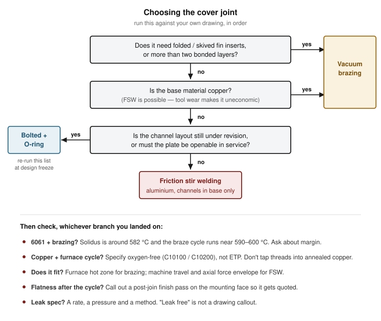
A decision sequence you can run against your own drawing
- Does the design need folded-fin or skived-fin inserts, or more than two bonded layers? If yes, it is vacuum brazing. Nothing else does this. Stop here.
- Is the base material copper? If yes, vacuum brazing unless you have a specific reason not to — and check that the drawing calls out oxygen-free copper and does not rely on threads tapped directly into annealed material.
- Is the base material aluminium, with channels in the base only? FSW is the default. If the drawing says 6061 and someone has proposed brazing, ask about solidus margin and about what happens to the temper.
- Will the plate ever need to be opened, or is the channel layout still under revision? If yes, bolt it and seal it, regardless of everything above, and re-run this list at design freeze.
- Does the part fit? Furnace hot zone for brazing; machine travel and force envelope for FSW. Check before, not after.
- What leak rate, at what pressure, by what method? Put a number on the drawing. Whichever process you pick, this is what the shop will actually be held to.
Send a drawing
If you already know which process you want, tell us and we will quote it. For aluminum-specific process selection, including when FSW or vacuum brazing fits the construction, see our aluminum cold plate machining guide. If you are not sure, send the drawing or even a sketch with the heat load, the coolant, the working pressure and the envelope, and we will tell you which of the three we would build it as and why — including the case where the answer is a bolted cover and a smaller invoice.
Before you send it anywhere, it is worth knowing what a good reply to an RFQ looks like — and what it tells you about the shop that sent it.
We run a manufacturability check on every drawing before we quote it, and we reply within one working day. More on what we machine and how we work is on the cold plate service page.Certification records are available on request once a project is under discussion.
If you have not fixed the channel geometry yet, start there instead — the constraints that govern channel layout are covered in Cold Plate Channel Design: Manufacturability Constraints, and several of them (minimum rib width, internal corner radii) directly determine whether an FSW lap weld along the rib tops is even possible.